Wanting to deepen the guidelines of the sizing of connecting rods,it is first necessary to identify the type of stresses to be resisted, namely a normal longitudinal compression and asimple flat bending without twisting, of obviously variable and periodic magnitude with the rotation of the crankshaft.
The nerve-wracking check is immediate:note the thrust agent on the connecting rod, it is sufficient to determine the resistant area of the rod and compare the applied effort with the yield load of the connecting rod.
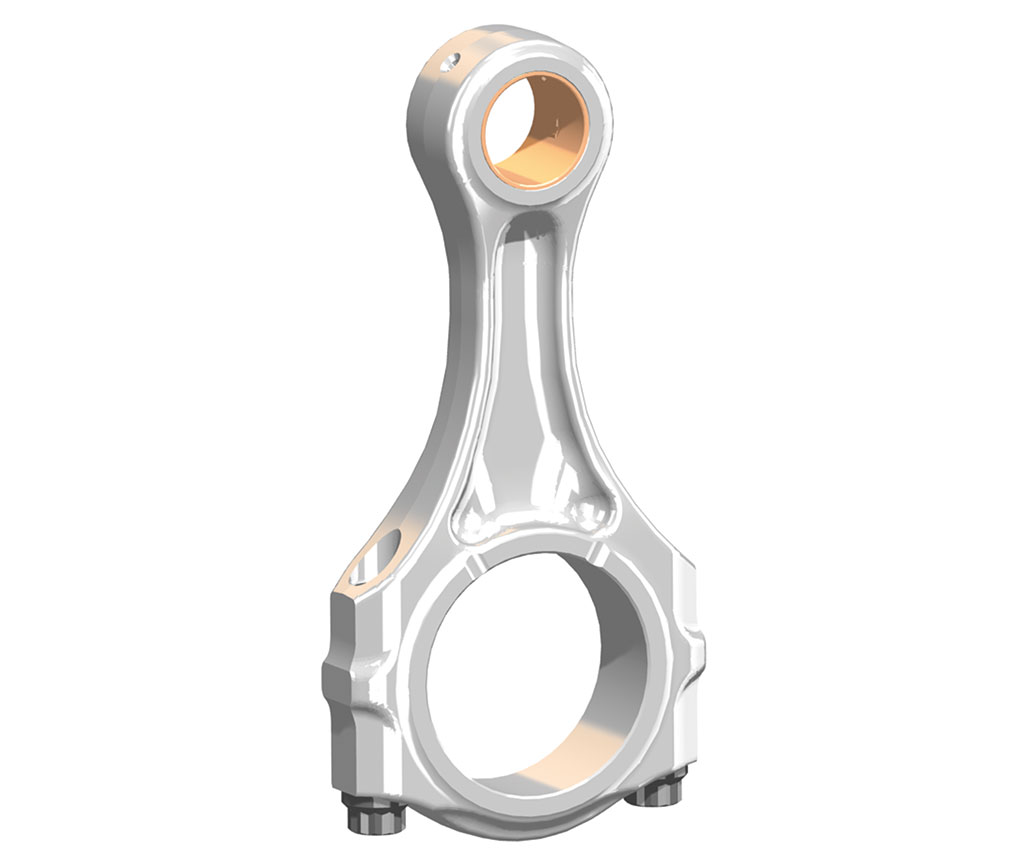
As for the peak load,the connecting rod is a slender structure that pushes compression tends to flex along the main axis.
The constraints of the structure are evidently different in the two orthogonal planes passing through this axis, since in one case it turns out to be a beam constrained at the ends with hinges (the head and the foot), while in the other it can be considered as a beam wedged between the piston and the goose neck.
It follows that the inflection characteristics and critical load are different in the two planes and must be analysed separately.
A further check on the connecting rod concerns the effects of flexional inertia , or theso-called “whiplash”.
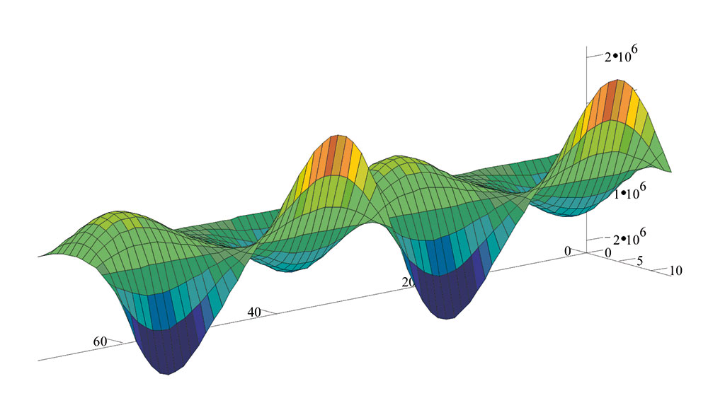
Imagining the very flexible connecting rod, one can guess how this, during each cycle, suffers alternating push-ups of the rod that produce the onset of fatigue phenomena in the material; Figure-4 shows the trend of stresses along the connecting rod as a result of the symmetrical alternating flexion resulting from the whiplash.
Similar checks take place in the design phase, after the thermal part has been defined and the thermodynamic characteristics of the thruster are known: with these premises, it is possible to establish the critical operating conditions (those in which the maximum stresses are produced).
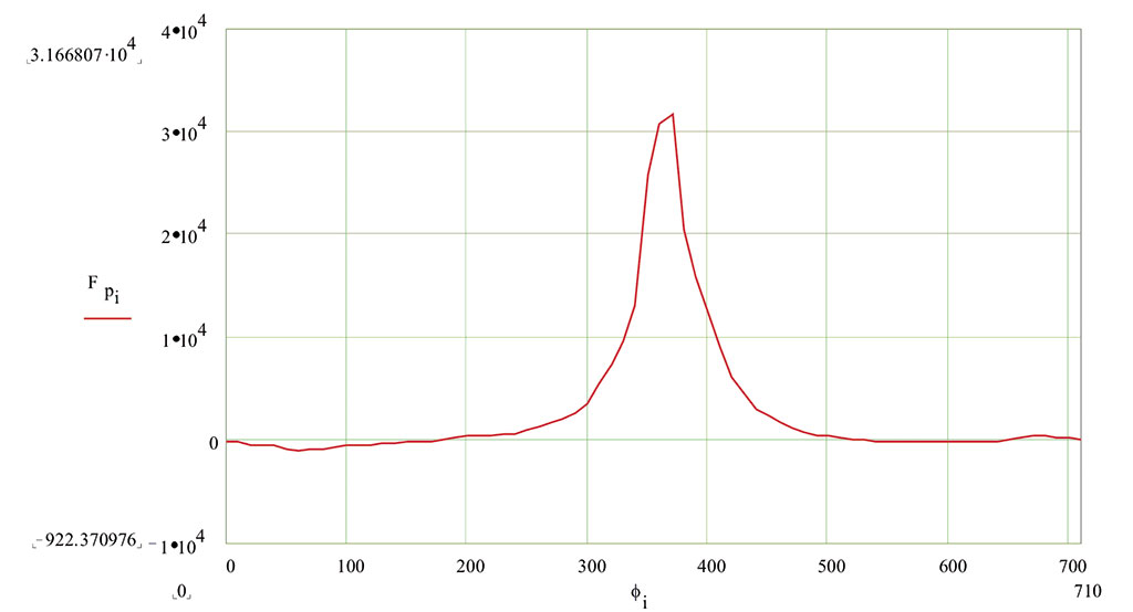
The maximum compression effort is around PMS (Upper Dead Point) as a result of combustion (Figure-5); the pressure on the piston sky gives rise to a longitudinal thrust to which only the inertia of the system is opposed.
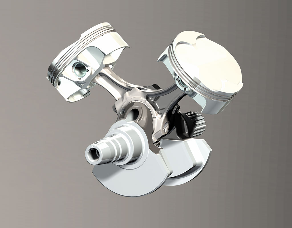
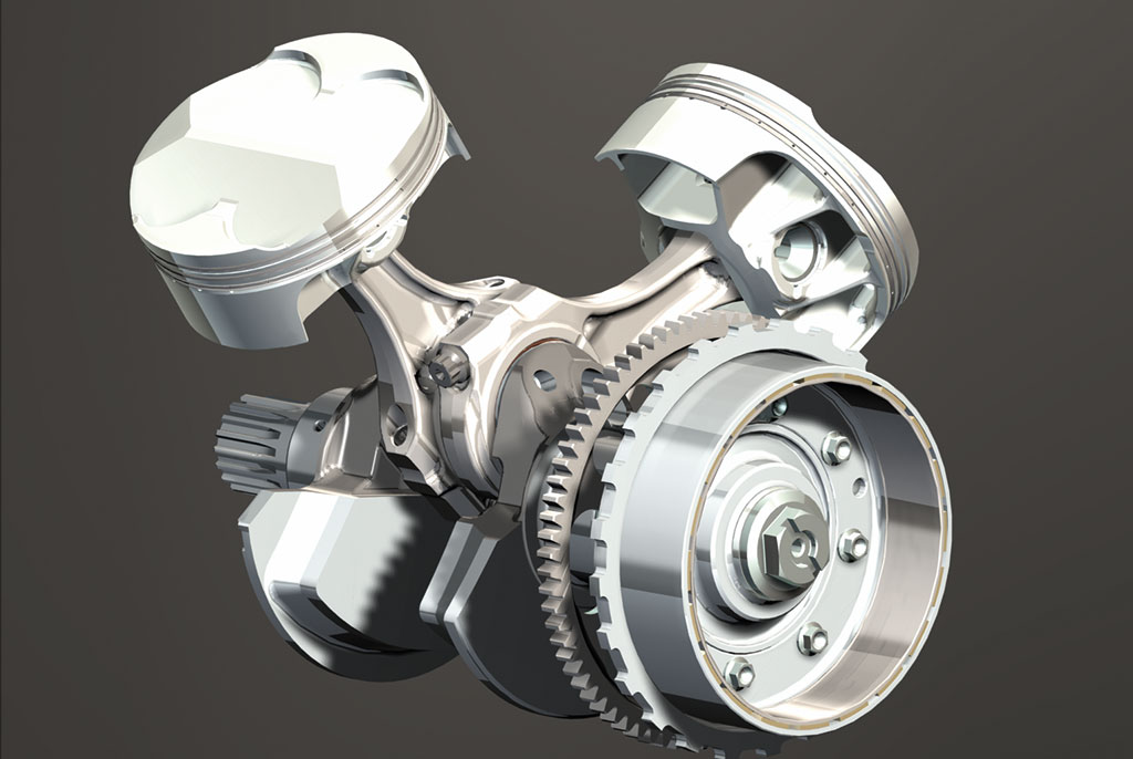
The different accelerations of the components correspond to inertia forces due to moving masses which are usually divided into two groups:one in solidarity with the connecting rodfoot (alternating masses)and the other with the crank button(rotating masses).
The first group contemplates the piston with the plug and the segments together with a fraction of the mass of the connecting rod (the 2/3 in the case of slender connecting rods with constant section); the second consists of the crank button, the connecting rod head and the residual fraction of the chard mass; it is also advisable to add to the crank button the reduced masses of all the eccentric parts rotating around the motor axis.
The inertia force of the alternating masses depends on the ratio (r/l) between the crank radius and the length of the connecting rod and the speed of rotation of the crankshaft, through a complex formula containing a series of terms with a negligible contribution, so that generally only the first two, called first-order and second-order, are considered.
Through some mathematical and physical simplifications it is possible to associate with them four components of the total alternating inertia force: they are two alternate forces of the first order (concord and discord) and two alternate forces of the second order (concord and discord).
In order to achieve the balance of these contributions, i.e. the cancellationof the imbalances and vibrations produced by the engine, it is necessary to take appropriate measures at mechanical level.
The force of the first order is easily eliminated by a counterweight of appropriate mass (in practice the imbalance given by the alternate motion with an appropriate weight on the crankshaft is balanced, such as to generate a force of inertia equal to and opposite to that of the piston).
That discord was said to be associated with a direction of rotation opposite to that of the crankshaft: wanting to eliminate it, here is the need for the adoption of the so-called balancing countershaft,which rotates in the opposite direction, but at the same speed as the main shaft.
It is clear that balancing second-order forces would
For this reason, it may also not be necessary to balancethem, especially in the case of multifracted thrusters in which the choice of an adequate architecture can eliminate them a priori.
As far as motorcycle engines are
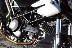
The 90° V-twin (Ducati) reveals the balance of the inertia forces of the first order alone., while those agreed are not: in practice, the adoption of the counterweight on the crank shaft is sufficient, without having to resort to the countershave, which, in this case, would only constitute a complication, a source of mechanical losses, weight increase and, therefore, less specific power.
In

SBK a Jerez: avanti tutta!
A Jerez de la Frontera, seconda tappa del campionato SBK, si ri-accende lo spettacolo con Ducati protagonista. Doppietta di Redding e secondo posto in gara 2 per Davies.
Bicilindrico a “L” Ducati: i motivi del successo
Analizziamo i motivi del successo della caratteristica architettura dei bicilindrici Desmo, nata per esigenze di raffreddamento e consolidata negli anni.