Over the years, in the motorcycle as well as in the automotive field, we have gradually become accustomed to ever higher performance, ever lower consumption, forgetting that until not many years ago the efficiency of motor vehicles was much lower.
There is a lot of talk about new technologies in engine management, with electronics to be the master in controlling the power supply, the fasatura and synchrony of all components; however, innumerable progress has also been made at the mechanical level, especially with regard to the real heart of the engine, namely the imbiellation, whichis entrusted with the task of convert the translational kinetic energy associated with piston movement into rotational kinetic energy.
It is the latter that we will deal with here, evaluating its components and principles of verification and sizing of moving elements.
In order to be right about the operation of a combustion engine, it may be useful to the comparison with a firearm, for example, a foreave rifle: once the gunpowder (fuel) and the projectile (the piston) have been inserted, the ignition of the charge produces a huge amount of gas in a very short time, so as to generate a very strong pressure and such as to fire the projectile out of the barrel.
In a four-speed engine a “bullet” is “fired” once every two laps: the problem therefore arises of turning this instantaneous and intermittent motion of the piston into a rotary motion as constant as possible over time; this function is the responsibility of the bodies that make up the environment.
To simplify matters, from now on we will refer to a single-cylinder engine, unless we subsequently make the necessary clarifications as the fractionation increases.
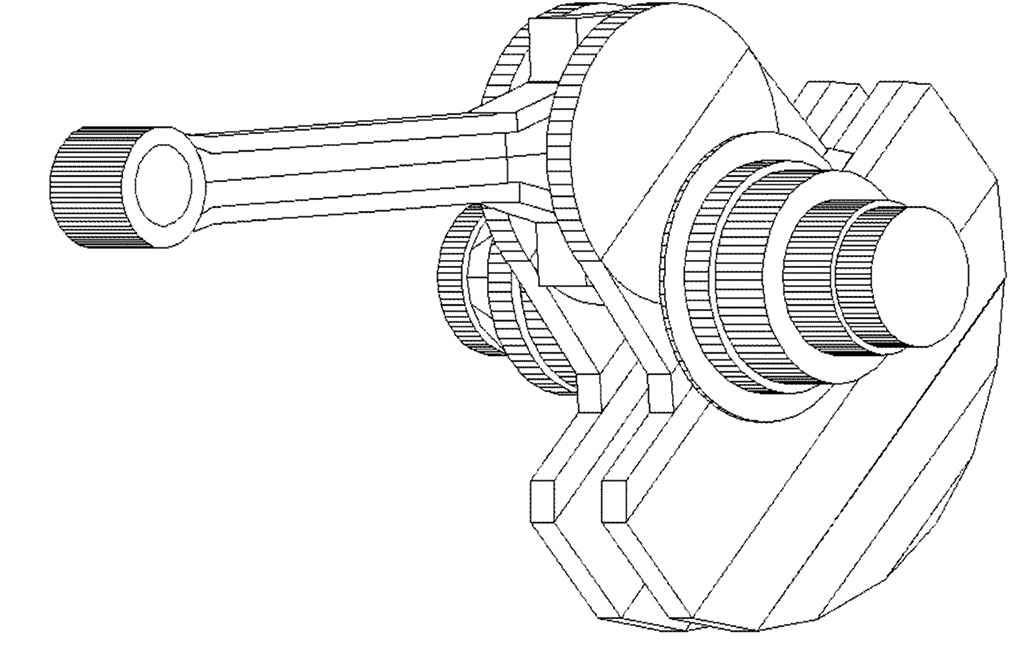
Figure-1 summarizes the basic components of the system: the piston is constrained by a plug to the connecting rod, with the latter representing the true key element of the mechanism and is in turn connected to the crank shaft, often referred to as the “gooseneck” for its particular geometry.
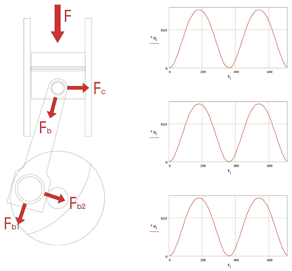
As mentioned, the driving thrust is the F-force produced by the combustion pressure(Figure-1); given any relative position of connecting rod and crank, the thrust can be broken down along the connecting rod (Fb component) and perpendicular to the cylinder (Fc component): the first force urges the connecting rod alternately for traction and compression, while the second does not provide the useful work (being directed perpendicular to the motion), but dissipates a certain amount of energy since, forcing the piston against the walls of the cylinder , generates friction resistance.
The Fb component, in turn, can be decomposed into Fb1, along the axis of the crank, and in Fb2, perpendicular to the crank.
The Fb1 component bends the crankshaft, while the Fb2 component is the one that multiplied by the crank arm generates the engine moment,clearly variable over time since it depends on the fluctuations of the F force and the position of the connecting rod.
Figure-2 shows the periodic trend of the position along the stroke, the speed and acceleration of the piston over the four times (720° of rotation of the crankshaft).
Commonly it is defined as a degree of irregularityof the motion, dependent on the extent of such fluctuations and inversely proportional to the inertia of the system: our engine, that is, necessarily does not tend to “turn” in a regular way.
For this reason, whenever it is necessary to standardize the rotary motion,a rotating mass is inserted on the axis of motion, having a high inertia value: this component is the flywheel, the mass of which therefore allows to obtain greater fluidity in the delivery of power sacrificing speed in increasing revolutions.
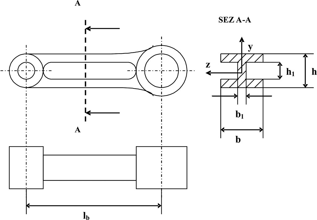
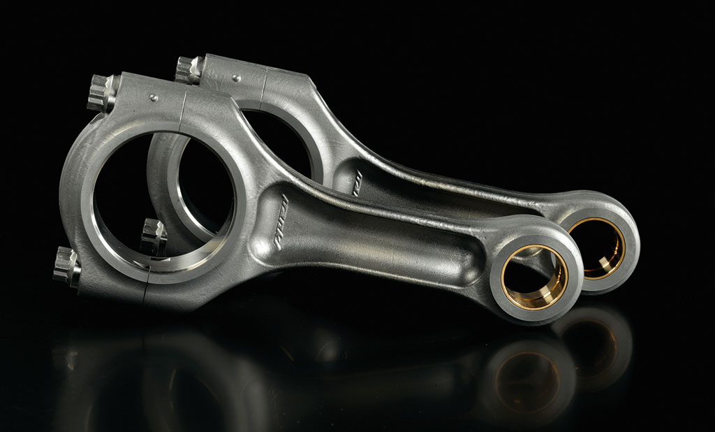
Reserving to deal with the very important events in which the piston is involved at another time, we will dwell on the so-called connecting rod-crank system:the connecting rod is commonly distinguished into three main sections: the foot (small extreme connected to the plug), the body and the head (tied to the crank).
For some particular applications the connecting rod can also be monolithic, but more often it has a decomposablehead, inside which a bushing of anti-refrigeration material is applied. The body is generally tubular, while h-sections are used for special applications; in any case, the barrel is commonly equipped with a through hole which is entrusted with the task of ensuring the lubrication of the plug and the foot (Figure-3).
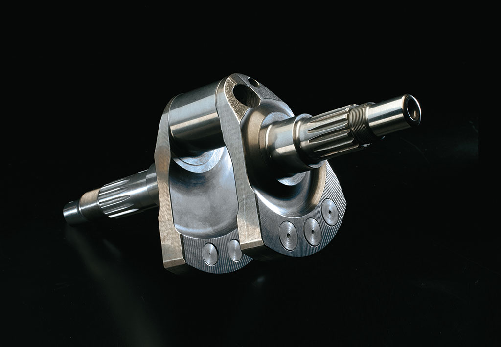
The gooseneck, on the other hand, is definitely variable for geometry depending on the fractionation and architecture of the thruster.
The choice of one configuration rather than another may depend on the need for space, balancing and arrangement of the accessory organs.
As we will analyse later, in principle we are trying to to approach as close as possible to the equilibrium conditions between the rotating and alternate masses,with obvious advantage for the strength of the crankshaft and for the effects due to the reduction of vibrations; to achieve this, the crankshamp is equipped with counterweights positioned at the antipodes of each crank button.
The geometry of the imbiellation is not determined a priori, since the choice of the length of the connecting rod and the realyse/stroke ratio does not depend on the unit displacement, but are defined at the design time according to the intended use of the engine and the materials used.
In motorsport jargon it is used to name engines “four” those with the same stroke as reasging, and “superquare” engines those with the greatest reasting of the race. In the motorcycle field, the latter formula is almost universally adopted for the advantages of short running for performance purposes. a combustion chamber with a high surface area and, therefore, the possibility of installing valves and their large diameter ducts, increasing the flow rate of incoming and outgoing gases.
By decreasing the path swept by the piston, its linear speed decreases and it is possible to achieve higher speeds,also by virtue of the possibility of adopting a shorter connecting rod, thus reducing the moving masses. It is in fact known that the length of the connecting rod is directly in relation to the piston stroke and how, logically, it changes the inclination of the same during operation.
It is also evident that, in addition to being lighter, a short connecting rod is in better condition than the tip load (the one that tends to bend a slender body, that is, long and thin, pressed at its ends), seeing at the same time reduced the amount of the lateral thrust on the wall of the cylinder.
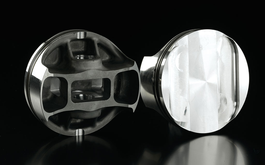
However, the larger surface area of the piston leads to an increase in globalpressure on the sky, i.e. on all the organs of the imbiellation; evidently, this goes in the direction of increasing the specific power of the thruster, but at the same time requires the proportionate sizing of the various components that remain subject to higher stresses.

SBK a Jerez: avanti tutta!
A Jerez de la Frontera, seconda tappa del campionato SBK, si ri-accende lo spettacolo con Ducati protagonista. Doppietta di Redding e secondo posto in gara 2 per Davies.
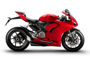
Il motore della Ducati Panigale V2
La bicilindrica della famiglia Superbike di Ducati si rinnova profondamente: piattaforma inerziale a sei assi, motore Superquadro da 955 cc rinnovato, Euro 5.